Measuring bouncing of China wind and rain sensors
A cheap China wind and a rain sensor were tested whether they experience contact bouncing, which would disturb the measurements.

The Wind Sensor
The wind sensor has a contact inside, which will be closed for 1/2 of the revolution of the wind wheel. The signal wire will be pulled high by a pull-up resistor at the remote end of the wire. This pull-up resistor can be a discrete resistor to +5 V or to +3.3 V depending on the voltage level of the corresponding input of the microprocessor.

The Rain Sensor Outside View

The Rain Sensor Inside View
The rain sensor is a rocker-type sensor which has a small cup which fills when rain drops flow out of the funnel of the sensor. This sensor also has a contact inside which closes for each movement of the rocker, when the small cup is full. The time of contact closure was measured to be grater than 60 ms in the device under test.

Contact bounce of the wind sensor
Bounce time when the switch closes is in the 100 us time range. This actually means that debouncing is necessary. For testing purposes a software debounce routine was implemented on an Arduino Uno which also provides the pull-up-resistor for the switch.
/*
 * From:  http://www.ganssle.com/debouncing.htm
 *
 * Count based
 * - From Ganssle's “Guide to Debouncing”
 * - routine called from timer interrupt or delay loop
 * - checks port bit, pushbutton depression, (bit will be grounded)
 * - returns '1' only once per button push, “pulsed output”
 * - acts like an edge detector
 *

static uint16_t  state = 0;

bool_t debounce() {
    state = (state << 1) | !rawKeyPressed() | 0xe000;
    if(state == 0xf000)
        return TRUE;
    else
        return FALSE; }
 */

/*
 * Debouncing implemented in a class ...
 */

class debounce {
    private: byte pin;
    uint16_t state = 0;

    public: debounce(byte pin) {
        this->pin = pin;
        pinMode(pin, INPUT_PULLUP);
        (void) update();
    }

    /*
     * The input pin is pulled high via the pull-up resistor and connected to GND via the switch
     *
     *                             value of state
     * first pass after reset:  1110 0000 0000 0001    return 0
     * after 12 false passes:   1111 1111 1111 1111    return 0
     * after 7 true passes:     1111 1111 1000 0000    return 0
     * after 12 true passes:    1111 0000 0000 0000    return 1
     * after many true passes:  1110 0000 0000 0000    return 0
     * after 5 false passes:    1110 0000 0001 1111    return 0
     */
    int8_t update() {
    state = (state << 1) | digitalRead(pin) | 0xe000;
    if(state == 0xf000)
        return 1;
    else
        return 0;
    }
};

debounce button1( 2 );

void setup() {
  pinMode(3, OUTPUT);
}

void loop() {

  /*
   * Debounce input pin and copy to output pin
   */
  digitalWrite(3, button1.update() );

  /*
   * This will give a 2ms high pulse on the falling edge, i.e. when the switch is pressed.
   */
  delay(2);

}
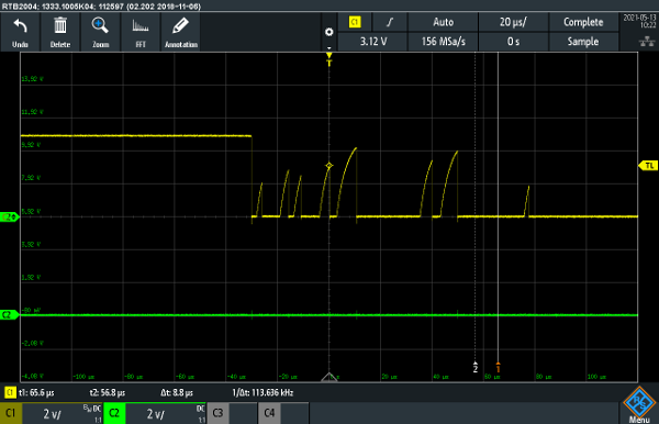
The following image shows the input signal and the de-bounced output from the Arduino Uno (channel 2, green):

De-bounced output of the wind sensor
The rain sensor did not show bouncing, but this may be a feature of the particular sensor, so debouning will be done as a precaution!
Note: This behavior may be related to the long cable of the rain sensor, whereas the wind sensor only had a short cable of approx. 50 cm length

De-bounced output of the rain sensor