For a recent project I experimented with alternatives to the very low end PIC 10LF322 chips. I made a small prototype board with the PIC 12LF1822 to perform some tests.

The 6-pin header directly connects to the PICkit 3 in-circuit debugger/programmer.

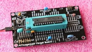
PIC12LF1822 Board with LED
The board is programmed in JAL [1], a medium high level language. JALv2 is a rewrite of Wouter van Ooijen’s famous Just Another Language. Besides the JAL language compiler, there is a library of support functions and samples for many PIC devices [2].
Here is a non-trivial code example of a “blink the LED” routine for the Microchip 12LF1822 device:
--
-- -----------------------------------------------------------------------------------
-- Title: Blink-a-led of the Microchip pic12lf1822 - WDT sleep version
--
-- Author: Karin Willers, Copyright (c) 2011, all rights reserved.
--
-- Compiler: 2.4o
--
-- Released under the BSD license (http://www.opensource.org/licenses/bsd-license.php)
--
-- Description:
--    Sample blink-a-led program for Microchip PIC12lf1822
--    Blink with WDT sleep
--
-- -----------------------------------------------------------------------------------
--

include 12lf1822                    -- target PICmicro

-- This program uses the internal oscillator
pragma target clock 1_000_000     -- oscillator frequency

-- configuration memory settings (fuses)
pragma target OSC        INTOSC_NOCLKOUT    -- internal oscillator (SCS <1:0> = 00)
pragma target PLLEN        P1                -- PLL off
pragma target WDT        enabled            -- watchdog on
pragma target DEBUG        disabled        -- no debugging
pragma target LVP        disabled        -- no Low Voltage Programming
pragma target MCLR        internal        -- reset externally
pragma target CLKOUTEN    disabled        -- no clk out
-- These configuration bit settings are only a selection, sufficient for
-- this program, but other programs may need more or different settings.
--

-- IRFC field is bits 6-3 of OSCCON register
--
-- OSCCON_IRCF = 0b1111                -- 16 MHz      HF
-- OSCCON_IRCF = 0b1110                --  8 MHz or 32 MHz HF
-- OSCCON_IRCF = 0b1101                --  4 MHz      HF
-- OSCCON_IRCF = 0b1100                --  2 MHz      HF
OSCCON_IRCF = 0b1011                --  1 MHz      HF
-- OSCCON_IRCF = 0b1010                --   500 kHz   HF
-- OSCCON_IRCF = 0b1001                --   250 kHz   HF
-- OSCCON_IRCF = 0b1000                --   125 kHz   HF
-- OSCCON_IRCF = 0b0111             --   500   kHz MF (default upon Reset)
-- OSCCON_IRCF = 0b0110                --   250   kHz MF
-- OSCCON_IRCF = 0b0101                --   125   kHz MF
-- OSCCON_IRCF = 0b0100                --   62.5  kHz MF
-- OSCCON_IRCF = 0b0011                --   31.25 kHz HF
-- OSCCON_IRCF = 0b0010                --   31.25 kHz MF
-- OSCCON_IRCF = 0b0001                --   31.25 kHz LF
-- OSCCON_IRCF = 0b0000                --   31 kHz    LF

--
-- Watchdog Timer Period Select bits (bits 5-1 of WDTCON)
--
-- WDTCON_WDTPS = 0b10010            -- 256  s nominal
-- WDTCON_WDTPS = 0b10001            -- 128  s nominal
-- WDTCON_WDTPS = 0b10000            --  64  s nominal
-- WDTCON_WDTPS = 0b01111            --  32  s nominal
-- WDTCON_WDTPS = 0b01110            --  16  s nominal
-- WDTCON_WDTPS = 0b01101            --   8  s nominal
-- WDTCON_WDTPS = 0b01100            --   4  s nominal
-- WDTCON_WDTPS = 0b01011            --   2  s nominal
WDTCON_WDTPS = 0b01010                --   1  s nominal
-- WDTCON_WDTPS = 0b01001            -- 512 ms nominal
-- WDTCON_WDTPS = 0b01000            -- 256 ms nominal
-- WDTCON_WDTPS = 0b00111            -- 128 ms nominal
-- WDTCON_WDTPS = 0b00110            --  64 ms nominal
-- WDTCON_WDTPS = 0b00101            --  32 ms nominal
-- WDTCON_WDTPS = 0b00100            --  16 ms nominal
-- WDTCON_WDTPS = 0b00011            --   8 ms nominal
-- WDTCON_WDTPS = 0b00010            --   4 ms nominal
-- WDTCON_WDTPS = 0b00001            --   2 ms nominal
-- WDTCON_WDTPS = 0b00000            --   1 ms nominal

enable_digital_io()                -- make all pins digital I/O

-- Specify the pin to which the LED (with serial resistor) is connected:
alias   led      is pin_A0
pin_A0_direction =  output

forever loop

led = 0
_usec_delay(50_000)
led = 1

assembler
sleep                    -- sleep for a while
nop                        -- pic12lf1822 continues here after WDT times out
end assembler

end loop
The code uses an inline-assembler code segment to put the processor to sleep during the time the LED is off to save power. Clock frequency and WDT sleep time are set by programming the appropriate processor registers.
[1] http://www.casadeyork.com/jalv2
[2] http://code.google.com/p/jallib/